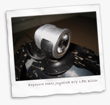
DIY LED Exposure Joystick Maxx killer
I’ve been tinkering in my shed and come up with an Exposure Joystick Maxx killer for a third of the price. It’s a great compliment to my Nightlightning iBlaast LED lights. Here’s a summary (with more photos on Flickr)…
If like me you enjoy a bit of tinkering then have a stab at this and save yourself a small fortune. This light uses the most powerful small LED currently in production (240 lumens) and is quite easy and cheap to make at approx £45 plus batteries (less if you nick them out of you child’s favourite toy!).
OK, it won’t have the finesse of the Exposure kit as it has a separate battery, but looks just as good and performs better than the Joystick Maxx at a fraction of the cost. Also, how cool is it to say you’ve made something this effective yourself?
There’s no reason why you can’t bar-mount this setup or even make 2 and have one on your helmet and one on the bars. Battery power/life and mounting will be your main considerations.
First, an overview
The main thing to worry about with LED’s is heat and with 1000mA, the diode gets hot. Hence the design of the light unit – the aluminium design radiates the heat away very effectively. When riding, my light unit is barely warm to the touch but soon heats up when I stop so I’d recommend turning it off if you don’t expect to get moving again within a few minutes. But its long enough to leave on while you wash the bike down and very handy when doing so in the dark!
The lens specified gives a superb and far-reaching spot beam with a reasonable amount of peripheral lighting.
The constant current converter is necessary when powering LED’s – regardless of the voltage input it delivers a constant 1 amp to the bulb and ensures a consistent level of brightness until the battery goes flat, rather than a gradual dimming or yellowing such as you get with halogens as the battery drops off.
You can also opt for the 700ma version, which will improve burn time but at the expense of brightness.
My set up gives me nearly 3 hours at full-power 240 lumens so more than enough for the average night ride. I’m using a li-ion battery that I purchased for my prototype version but AA’s will be more convenient and just as effective. 2700mAh AA’s will give you over 2.5 hours of burn time.
The input voltage can be anything from 4.8 to 32 volts, the important factor is the power (or amperage) – in simple terms, divide the amperage (in mAh) of your battery by 1000 (the output of the converter) to give you your burn time.
The thermal epoxy is important as it helps ensure the heat is transferred efficiently to the light unit and remains strong when the temperature rises.
I’m not going to write a full instruction book on this, so commonsense is required but please contact me if you have any queries or want me to email you the drawing to get the light body machined.
| Component | Sourced from |
|---|---|
| Seoul P4 Z-LED (240 lumens) | www.led-tech.de |
| 1000mA Buckpuck Constant Current Converter | www.ultraleds.co.uk |
| Luxeon Collimator Lense and Holder LXHL-NX05 | www.ultraleds.co.uk |
| Exposure Joystick Helmet Mount | www.chainreactioncycles.co.uk |
| 4 x 2700mAh Rechargeable AA batteries | Various |
| Battery Holder | Various |
| Connectors for power lead | Various |
| Thermal epoxy resin | www.led-tech.de |
| Suitable flex (I used the 2 core wire from an old mobile phone charger) | Various |
| Inline switch, preferably waterproof | Various |
| Silicone sealant | Various |
| Heatshrink | Various |
| Insulating tape | Various |
First off, you need to get yourself a friendly machinist to knock-up the light unit from aluminium. Expect to pay around £15-£25 depending on how well you know them!
You can get the hole for the wire drilled wherever you want but going in from the side is best in order that the wires can enter the casing adjacent to the small semi-circular cutouts in the LED base.
A few tips
- When you solder wires, make sure you tin (lightly solder) each one first before attempting to solder them together – it really helps
- After soldering the joints on the wires, seal them with heatshrink and then wrap insulating tape around them. Soldered joints are not strong and this helps to keep them firm and supported and free from movement-induced stress
- When the wires are soldered to the LED, try to keep them as flush as possible or they’ll prevent the lens holder sitting down far enough on the LED. I ended up shaving plastic off part of the bottom of the lense holder with a Stanley knife where it butts up against these joints
- The Exposure helmet mount I’ve used is good but you may think of a better one – its up to you. If you do opt for this one, you’ll need to ‘modify’ (ie shave plastic off it with a knife) in order for it to fit the recess on the light unit snugly
- Put the heatshrink over the wires first before soldering them!!
That’s it, the rest is up to you. May not go easy first time round – soldering takes practice. Just take your time and go enjoy your creation!
View the document for the light body here (do right click/save as to download it)
Disclaimer – I am no electrical whizzo so I may not be 100% factually correct in what I say but it works for me and will for you too!

About the author
There are 23 comments on ‘DIY LED Exposure Joystick Maxx killer’
We love to get comments from our readers - if you've spent a few moments to comment, thank-you.
If you haven't had a chance yet, jump to our comments form if you have something to say.
Ashley Saunby says:
Hi, just read up on Colins DIY LED light and I think this on my helmet would compliment my lights. Any chance of emailing me any drawings etc. etc. please?
Add a new comment, or
Posted on March 16, 2008 at 6:24 pm
Colin says:
Hi Ash, by all means. Its so good you can even run it on it own but best as you say to compliment your main light.
I’ve emailed you the drawing so good luck and do keep us posted on your progress.
Add a new comment, or
Posted on March 16, 2008 at 10:53 pm
Gareth says:
Thanks for the inspiration, see the pics of my homebrew setup at :
I got the parts as you suggested – LEDtech.de and ultraled.co.uk – luxeon type leds and collimators. I turned the bodies from a piece of 30mm aluminium, parted off the end cap, bored out the main hole a little more, so that the led and lens is held in mostly by the end cap. The hole in the end cap is exact diameter as the end of the lens, inside the main body is a bit wider. Applied some thermal paste on the bottom of the led. Turned the cooling fins and rubber band grooves. Drilled hole in bottom for the wire, and glued this in place. End cap is now held on with four 8mm M3 allen head bolts.
I’m going to run two in series with a 1000mA buckpuck constant current device.
Add a new comment, or
Posted on March 17, 2008 at 3:12 pm
Colin says:
Gareth, thats very impressive, a work of art and very useful info to anyone else who fancies a go.
By the way, Trailtech offer a small waterproof switch for £6 which works well.
Add a new comment, or
Posted on March 17, 2008 at 3:22 pm
Ashley Saunby says:
Just starting to buy in the parts but I’m struggling to find the thermal epoxy resin at led-tech site. Could you point me in the right place please? Also I presume the led is the single emitter and not the starlight?
Add a new comment, or
Posted on March 18, 2008 at 11:00 pm
Colin says:
Sorry, they describe the thermal epoxy ‘heat conductive glue’. Its the first item in the Tools and Materials section under the Technic and Supply category. Part number LT-0775
The LED you need is the High Power Seoul 3.5W P4 Star, 240 lumen in white. Part number LT-0980
The Star is basically an emitter diode that is pre-mounted on a small heatsink, ready for you to mount in the casing you’ll be making. To use the emitter only would be way too fiddly
Add a new comment, or
Posted on March 19, 2008 at 9:31 am
Gavin Hinds says:
Hi there, a brilliant little light. I also am looking for something to compliment my iBlaast.
Can you email the drawings of the housing? Thank you
Add a new comment, or
Posted on June 9, 2008 at 12:47 am
Alan Henstock says:
Wow, sounds like a fantastic helmet light.
Can you email drawings of the housing?
Thanks
Add a new comment, or
Posted on September 27, 2008 at 9:48 pm
Matt says:
Alan, you’ve got mail. Good luck with the light, let us know how you get on.
Add a new comment, or
Posted on October 1, 2008 at 10:22 pm
Muddymoles says:
Cycle Show 2008 at Earls Court
An overview of some of the bikes and products that stood out from this years Cycle Show 2008 at Earls Court.
Add a new comment, or
Posted on October 13, 2008 at 12:24 pm
Dave says:
Could someone who has the drawings email them to me please… this is looking viable! 🙂
thanks
Add a new comment, or
Posted on October 29, 2008 at 5:08 pm
Colin says:
Hello Dave, just click on the hyperlink in the last paragraph and it opens up an excel file I used to cobble the drawing together with.
Most certainly is viable and soon to be upgraded with over 300 lumens of Cree R2 diode.
Add a new comment, or
Posted on October 29, 2008 at 10:31 pm
Roger says:
Colin,
Not bad for a non engineer !.Save a funtune not buying and making yourself and far more satisfying.I have at last finished mine 720 lumens,3 hour burn time and a titanium housing.Joysick helmet mount(wiggle).Battery source is via model web site you can get good quality small Lipo’s for about £20.00.You then just need charger and power supply.
I might post some pics soon.Although currently mounted on helmet I will make a smaller unit as I can now get a 900 lumens LED but battery life a issue.
Pictures to follow
Add a new comment, or
Posted on November 24, 2008 at 1:56 pm
George says:
I am very keen to try this but not sure exactly what constant current connector to use as there are a few on the http://www.ultraleds.co.uk site, any chance you can pass on the model number.
I am also thinking of driving a rear red LED similar to the Exposure Red Eye, should I buy a separate converter for this with a lower current, or is there another way around this as i don’t need it as bright and want to save on battery power?
Thanks
Add a new comment, or
Posted on December 3, 2008 at 12:36 pm
dave says:
Hi again. I’m working out my detailed design (before committing to buy anything) and have a couple of questions:
q1
The joystick lights I’ve seen are about 15mm diameter… have the mount diameters changed? Is there a v1 mount that I need to source?
q2
how have people held the internals into the casing? I’ve never worked at this scale before so anyone else’s experience would be appreciated!
q3
really dumb question – how does the emitter get held into the lens? From manufacturers’ website pictures it looks to me as though the lens is going to fall off!
thanks in advance,
DL
Add a new comment, or
Posted on December 5, 2008 at 3:57 pm
Colin says:
Firstly George – I’ll dig out my invoice from ultraleds and let you know the part number.
As for the exposure Red Eye, you wouldn’t be popular on our night ride giving us all retina burn !!!!
If you got the converters rated at 350mA then that would be plenty enough, though Dave C may have a better idea by using a resistor or something.
Please keep us posted and send in your pics when you’re done. Theres a lot of folks diy-ing there lights and the blog gets a lot of traffic.
I’m just upgrading mine to an R2 diode so I don’t lose touch in the light-arms race!
Add a new comment, or
Posted on December 5, 2008 at 4:49 pm
Colin again says:
Hello again Dave
I think you’re right that the exposure lense is 15mm but the body i’m sure is 25-27 mm diameter (though there may be different sized models out there)
Q2 I’ve used thermal epoxy resin very successfully. In upgrading my diode, I have managed to break it apart again but its strong stuff. I also used a small amount to hold the lense holder in the light body and the lense to the holder itself
Q3 The lens clips into the lense holder and this whole assembly just ‘sits’ on the emitter. As above, I then apply a bit of the epoxy to make sure the assembly stays put
Hope that helps and again, do tell us how you get on a send some pics if poss.
Rgds
Colin
Add a new comment, or
Posted on December 5, 2008 at 5:01 pm
Colin yet again says:
The buckpuck part number is 03023-D-N-1000
Just a note to all – if you are using Cree emitters, the luxeon optics won’t fit. The base of the diode the lense sits on is wider.
I’ve just ordered some from Carclo in Slough to see what they’re like.
As we’re all finding, its not all about lumens, just as important is the quality of the optic.
Add a new comment, or
Posted on December 6, 2008 at 9:27 am
Jeff says:
Colin,
Thanks for the inspiration too! I’m currently assembling two to run off a single battery pack and current converter (as Gareth has? I can’t see his pics).
Anyway, I’m trying to figure out what voltage to aim for on the battery pack. The led-tech site suggests that resistors are required, depending on the battery voltage and number of LED’s – did you need to take this into account? (or anyone else who has had a go at this?).
I’m nearly there, any help would be appreciated!
Add a new comment, or
Posted on January 7, 2009 at 9:47 pm
Dave says:
Jeff,
I’ve just finished mine and the voltage wasn’t an issue as the Buckpuck driver handles from 5-32 volts and, unless you have a super-strong neck, 32v will be heavy!
I ran mine on 4x2600mAh AA batteries producing 6.3v (measured) and it was perfectly happy for 90 minutes. It perhaps started to dim (or perhaps I was starting to notice less) but I was still getting 5v out when I got home.
If I can find a lighter, higher voltage battery with slightly higher capacity (eg a camera battery) then I may switch that in but otherwise 6.3v dropping to 5v was fine.
Add a new comment, or
Posted on January 15, 2009 at 11:07 pm
Neil says:
Hi Colin, I am building one of these lights and am thinking of fitting the Cree R2 diode, can you tell me where you have sourced yours from please?
Thanks Neil
Add a new comment, or
Posted on January 27, 2009 at 1:53 am
Markus Lobs says:
great Advise !
i bought similar stuff here in Germany from http://www.eos-led.com
Add a new comment, or
Posted on April 12, 2010 at 11:30 am
Related: Cycle Show 2008 at Earls Court | News, 2008 | Muddymoles: Mountain biking (MTB) in the Surrey Hills and Mole Valley